Wednesday, September 9, 2015

NAS - ARP

NAS - ARP

ARP is Allocation and Retention Priority. Understanding ARP requires to chase multiple Specs for its functionality.

As per 3GPP TS 36.413 version 12.3.0 Release 12

ARP contains 3 Mandatory IE's:
1. Priority Level
2. Pre-Emption Capability
3. Pre-Emption Vulnerability

Priority Level - Range: 0 to 15
0 - Logical Error
1 - Highest Priority
14 - Lowest Priority
15 - No Priority

Pre-Emption Capability
It has 2 Enumerated Value:
1. shall not trigger pre-emption, - Cannot preempt other bearers during resource crunch
2. may trigger preemption - Can Trigget preemtion of other bearers during resource crunch

Pre-Emption Vulnerability
It has 2 Enumerated Value:
1. not preemptable - This bearer cannot be pre-emptable by other bearers

2. preemptable - This bearer can be release during resource crunch by other bearers.

As per spec 23.401 Rel 11, 4.7.3 Bearer level QoS parameters

1. The primary purpose of ARP is to decide whether a bearer establishment / modification request can be accepted or needs to be rejected due to resource limitations (typically available radio capacity for GBR bearers).

2. The priority level information of the ARP is used for this decision to ensure that the request of the bearer with the higher priority level is preferred. In addition, the ARP can be used (e.g. by the eNodeB) to decide which bearer(s) to drop during exceptional resource limitations (e.g. at handover).

3. The pre-emption capability information of the ARP defines whether a bearer with a lower ARP priority level should be dropped to free up the required resources. The preemption vulnerability information of the ARP defines whether a bearer is applicable for such dropping by a pre-emption capable bearer with a higher ARP priority value.

4. Once successfully established, a bearer's ARP shall not have any impact on the bearer level packet forwarding treatment (e.g. scheduling and rate control). Such packet forwarding treatment should be solely determined by the other EPS bearer QoS parameters: QCI, GBR and MBR, and by the AMBR parameters.

NOTE 1: The ARP is not included within the EPS QoS Profile sent to the UE. So UE will not know about ARP configurations eventhough its one of a Bearer Qos Parameter.

NOTE 2: The ARP should be understood as "Priority of Allocation and Retention"; not as "Allocation, Retention, and Priority".

NOTE 3: Video telephony is one use case where it may be beneficial to use EPS bearers with different ARP values for the same UE. In this use case an operator could map voice to one bearer with a higher ARP, and video to another bearer with a lower ARP. In a congestion situation (e.g. cell edge) the eNodeB can then drop the "video bearer" without affecting the "voice bearer". This would improve service continuity. ETSI 3GPP TS 23.401 version 11.3.0 Release 11 65 ETSI TS 123 401 V11.3.0 (2012-11)

NOTE 4: The ARP may also be used to free up capacity in exceptional situations, e.g. a disaster situation. In such a case the eNodeB may drop bearers with a lower ARP priority level to free up capacity if the pre-emption vulnerability information allows this.

Tuesday, September 8, 2015

LTE - Signalling Radio Bearers

LTE - Signalling Radio Bearers

Lets talk about the Radio Bearers in LTE. The Radio bearers exactly comes in the RRC layer with a Logical Channel Mapping. The Radio bearers are classified as Signalling Radio Bearers - SRB's & Data Radio Bearers - DRB's

Signalling Radio Bearer's:

There are 3 SRB's - SRB0, 1 & 2

SRB0:
SRB0 is mapped to CCCH in Uplink & Downlink. The RRC messages RRC Connection request & RRC Connection Setup will be transmitted in SRB0

SRB0:
Direction: UL/DL
RLC - Mode: TM (Transparent Mode)
Logical Channel: CCCH
Logical Channel Group: 0

Messages Transmitted in SRB0:

1. RRC Connection request
2. RRC Connection setup
3. RRC Connection Reestablishment
4. RRC Connection Reestablishment Reject

SRB1:
SRB1 is mapped to DCCH in uplink & downlink. RRC messages & RRC with NAS piggybacked messages prior to the establishment of SRB2 will be transmitted in the SRB1

SRB1:
Direction: UL/DL
RLC - Mode: AM (Acknowledged Mode)
Logical Channel Group: 0

Messages Transmitted in SRB1:

1. RRC Connection setup Complete,
2. RRC Connection Reconfiguration,
3. RRC Connection reconfiguration Complete
4. RRC Connection Re establishment Complete.
5. Security Mode Command &
6. Security Mode Complete,
7. UE Capability Enquiry,
8. UE Capability Information,
9. Measurement reports. etc...

SRB2:
SRB2 is mapped to the DCCH in Uplink & Downlink, but after the integrity & Ciphering protected. All the NAS piggybacked messages for the UE, will be transfered in SRB2 if its present hereafter.
For the SRB2 & DRB's to establish, the AS has to be always Integrity Protected. SRB2 establishment will be taken place with the help of RRC connection reconfiguration coming from E-UTRAN to UE

SRB2:
Direction: UL/DL
RLC - Mode: AM (Acknowledged Mode)
Logical Channel: DCCH
Logical Channel Group: 0

Messages Transmitted in SRB2:

1. UL Information Transfer
2. DL Information Transfer

Note: SRB1 will always have the high priority in transferring the messages over SRB2. LCID is only for DRB's. SRB's will not have the Logical Channel Identity IE.

LTE - BEARERS

LTE - DATA BEARERS

We all know the Default & dedicated bearers established in LTE. Do we know how many such bearers can be established???

Any works only in NAS will say 2 to 11, based on the EPS bearer Identity. If we dig deep across the following specs of NAS, RRC, MAC & UE conformance, we can come to a conclusion that only 8 bearers are successfully established at a time for a UE.

Funda behind the Bearers:

NAS identifies the Bearers based on the EPS - bearer identity which has a range from 0 to 15

In that 0 to 4 are reserved, so 5 to 15 are used for EBI allocation for every bearer that is created.
This counts to 11 from EPC perspective.

From the RRC spec, 36.331 rel 12.3, MaxDRB's per UE = 11

From the RRC spec, 36.331 rel 12.3, LogicalChannelIdentity for DRB = 3 to 10 (Integer values)

Each Bearer will be mapped from NAS/RRC/MAC as EBI/DRB/LCID

Since the LCID in MAC is having the range from 3 to 10, only 8 DRB's can be established per UE @ a time in LTE. So the Limitation comes in the Logical Channel Identity mapping for the data bearers.

From 36.508, DRB configuration is as follows:

If EBI = X + 4; 
Then
DRB ID = X && LCID = X + 2;

Since we have already seen that the Logical Channel Identity range is from 3 to 10, LTE cannot have more than 8 bearers @ a time as of now till Rel 12.3

Hope this helps in better understanding.

Monday, September 7, 2015

LTE - Measurement Reports

LTE - Measurement Reports

We all heard of the word "Handoff". UE moving from the serving cell to a Neighbour cell. 2 Level of functionalities happens here for this process. NAS level control Messages & AS level control Messages.

We see the AS level messages which triggers the Handoff. the Basic Funda behind Handoff is when the Target cell becomes better than the Serving Cell, UE will move on to the better cell for better user experiences.

So How UE will come to know that the Target Cell is better than the Serving Cell? Here comes the Measurement Reports for that purpose. The Measurement reports are carried by the RRC Connection Reconfiguration message in the Connected state.

There are as many as 8 Measurement Events for this purpose. They are classified as Intra-system Handover related events & Inter system Handover related Events.

Intra-system Handover:

This is TAU within the LTE cells moving from source to target. It can be of same frequency or different frequency based on the availability & configuration of the Target Cell.

The measurement Events used for this Handover are A1, A2, A3, A4, A5, A6

A1 - Serving becomes better than Threshold
A2 - Serving becomes worse than Threshold
A3 - Neighbour becomes Offset better than Primary Cell
A4 - Neighbour becomes better than Threshold
A5 - Serving becomes worse than Thresold1 & Neighbour becomes better than Threshold2
A6 - Neighbour becomes Offset better than Secondary Cell


Inter-System Handover:

This is IRAT handover moving from LTE Cell to UMTS Cell or GSM cell based on the availability of the Cell.

The measurement Events used for this Handover are B1 & B2


B1 - Inter RAT neighbour becomes better than Threshold
B2 - Serving cell becomes worse than Threshold1 & Inter RAT neighbout becomes better than Threshold2

All the Thresholds mentioned above are configurable in the E-UTRAN Provisioning file. Once the Events get triggered, Handover happens accordingly.

Spec reference: 36.331, Sec 5.5 Measurements.

Tuesday, August 18, 2015

LTE - RACH Procedure

LTE RACH Procedure

RACH Procedure is the 1st procedure through which UE will send its first Uplink message to the Network element EnodeB. Since its the 1st message sent by UE in UL, its MSG1

1. UE sends Rach Request in MSG1 to EnodeB
2. EnodeB sends Rach Response in MSG2 to UE with Temp_C_RNTI
3. UE sends UE Identification Message in MSG3 to EnodeB
4. EnodeB sends Contention Resolution Message in MSG4 to UE


 UE                                                                          EnodeB


------------------- RACH REQUEST in MSG1 ----------------->


<------------------- RACH RESPONSE in MSG2 ---------------


--------- UE IDENTIFICATION MESSAGE in MSG3 ------->


<--- CONTENTION RESOLUTION MESSAGE in MSG4 --


Note:

Important points to remember about the RACH procedure:

1. RRC connection request will be sent in MSG3 to EnodeB by UE with UE- Identity filled with a Random Value (Random value will be used when the RRC connection Request will be sent for the 1st time by the UE after Switch ON, i.e., UE is not having any identifiers with it.)

2. Once the RRC connection request is received by EnodeB, MSG4 will be sent by the EnodeB MAC  to UE, since MSG4 is a MAC level Message. (All MSG1, MSG2, MSG3, MSG4 are MAC level messages)

3. After RRC connection req is processed, RRC Connection Setup will be sent by EnodeB to UE on Signalling Radio Bearer 0 - SRB0 with a C- RNTI assigned & details to setup the SRB1.

MSG 1:


LTE Random Access Request (MSG1) Report
Version                  = 5
Preamble Sequence        = 25
Physical Root Index      = 129
Cyclic Shift             = 325
PRACH Tx Power           = -44 dBm
Beta PRACH               = 242
PRACH Frequency Offset   = 0
Preamble Format          = 0
Duplex Mode              = FDD
Density Per 10 ms        = 1
PRACH Timing SFN         = 907
PRACH Timing Sub-fn      = 1
PRACH Window Start SFN   = 907
RACH Window Start Sub-fn = 4
PRACH Window End SFN     = 908
PRACH Window End Sub-fn  = 4
RA RNTI                  = 2
PRACH Actual Tx Power    = -44


MSG 2:

LTE Random Access Response (MSG2) Report
Version                 = 1
SFN                     = 907
Sub-fn                  = 6
Timing Advance          = 0
Timing Advance Included = Included
RACH Procedure Type     = Contention Based
RACH Procedure Mode     = Initial Access
RNTI Type               = TEMP_C_RNTI
RNTI Value              = 53


MSG 3:

LTE UE Identification Message (MSG3) Report
Version                   = 1
TPC                       = 3
MCS                       = 1
RIV                       = 302
CQI                       = Disabled
UL Delay                  = Don't Delay
Hopping Flag              = Disabled
SFN                       = 908
Sub-fn                    = 2
Starting Resource Block   = 2
Num Resource Blocks       = 4
Transport Block Size Index = 1
Modulation Type           = QPSK
Redundancy Version Index  = 0
HARQ ID                   = 2

MSG 4:


LTE Contention Resolution Message (MSG4) Report
Version              = 1
SFN                  = 908
Sub-fn               = 7
Contention Result    = Pass
UL ACK Timing SFN    = 909
UL ACK Timing Sub-fn = 1

Thursday, August 6, 2015

LTE - STACKS

LTE - STACKS

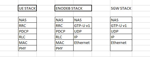
Lets see the LTE complete Stack architecture with respect to MME & SGW from the EnodeB. EnodeB is nasically a protocol converter, which converts the messages received from MME with a different set of Stack layers. It Take the NAS messages & encapsulate it to the OTA stack & send it to UE's.

In Downlink, EnodeB receives 3 kind of stack messages.

1. From MME (Control Plane - S1 Interface)
2. From SGW (Data Plane - S1-U Interface)
3. From neighbour EnodeB (Control & Data Plane - X2 interface)

Lets see the Stack between UE, EnodeB & MME


Similarly you can see the Stack between UE, EnodeB & SGW:


The EnodeB to EnodeB stack comprises control & Data Planes in the X2 Interface for carrying the control information & data respectively.

Stack for X2 Interface control plane:

Stack for X2 Interface Data Plane:

I hope the you can understand the complexity in the EnodeB stack & its importance in the LTE architecture.

Wednesday, August 5, 2015

LTE - Terminologies & Explanations

LTE - Terminologies & Explanations

PLMN ID is a Public Land Mobile Network Identifier; serves to PLMN unique identification
PLMN ID (not more than 6 digits) = MCC + MNC

MCC is a Mobile Country Code; assigned by ITU; (3 digits)

MNC is a Mobile Network Code; assigned by National Authority; (2 or 3 digits) If the 2 digit MNC is used, then the PLMN will be like ex: 262-09 for 3 didgit MNC, PLMN is like: 262-009

MSIN (MSISDN) is a Mobile Subscriber Identification Number; assigned by operator; (10 digits)

IMSI is an International Mobile Subsciber Identity; serves to uniquely identify a mobile (LTE) subscriber; not more than 15 digits) IMSI will be 14 digits or 15 digits based on the MNC with 2 digits or 3 digits.
IMSI = PLMN ID + MSIN = MCC + MNC + MSIN

ECGI is an E-UTRAN Cell Global Identifier; serves to identify a Cell in global (globally unique); EPC knows the UE location based of ECGI
ECGI (not more than 52 bits) = PLMN ID + ECI

ECI is an E-UTRAN Cell Identifier; serves to identify a cell within PLMN; (28 bits)
ECI = eNB ID + Cell ID

Cell ID is a CELL identifier; serves to uniquely identify a cell within eNB; (8 bits)

eNB ID is an eNodeB Identifier; serves to identify an eNB within PLMN; (20 bits)

Global eNB ID is a Global eNodeB Identifier; serves to identify an eNB in global (Globally unique); (max 44 bits)
Global eNB ID = PLMN ID + eNB ID

Note: The physical Cell ID is different from the Cell ID mentioned above. The Physical Cell ID is used to decode the enodeB signalling by the UE @ phy layer. The Cell ID mentioned above is used by the NAS & RRC layers for EPC management purposes. The most important use of Phy Cell ID is:

Interference to reference signals from reference signals of other cells is eliminated by Physical Cell Identity

Reference: 3GPP 36.508 - Conformance Testing.